3D PIPELINE MAPPING
General Method Statement
- This General Method Statement outlines the operational procedures of Pipeline Mapping Systems when the system is propelled by means of a pulling wire only.
- Despite the fact that certain safety recommendations are made, local Health and Safety regulations (i.e. at the location of the job site) prevail over the recommendations in this document.
Technological Principles
The DuctRunner™ Technology
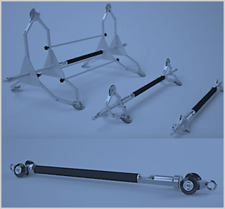
The DuctRunner™ inertial mapping technology fundamentally consists of 3 major components:
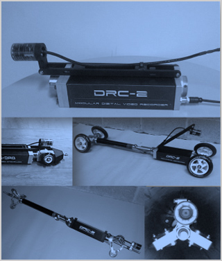
The Orientation Measurement Unit (OMU) contains all inertial sensors as well as a range of secondary sensors. The OMU is carefully calibrated to determine the alignment of each mechanically assembled sensor to within 0.01°.
The OMU is fully autonomous, i.e. it is battery powered and the data logged is stored internally during a measurement run. This eliminates the need to drag a data and/or power cable behind the system. Also, autonomy means that it does not need to be traced above ground as it moves through a pipe and thus can travel to any depth and underneath any obstacle (such as rivers, railways, highways, buildings, etc.).
An application-specific housing and centralizing system that typically contains the odometers to record the speed of travel.
Proprietary X-Traction® and X-View® data processing software.
These software programs convert the autonomously logged data by the OMU and odometers to an accurate 3-dimensional line in the same coordinate system as the given coordinates at the entry and exit points.
The unique approach taken by Reduct means that it is not necessary to know the exact position of the OMU as it travels from the entry point (A) to exit point (B). Rather, the software establishes where it has been after it is retrieved from the pipe.
Essentially, for each sample, the X-Traction® software calculates the angular change compared to the previous sample. The sample length is then derived from the odometer log. When the calculated vectors are placed in sequence, the path travelled is reconstructed, which is then linked to the known coordinates of A and B to obtain the final result in the chosen coordinate system. The resulting output can then be further processed to various forms of information.
System Accuracy
The calibrated accuracy of an OMU is 15cm in XYZ over a 500m distance between way-points assuming the following mapping conditions:
- HDD shaped track
- Temperature change < 5°C
- Pulling speed of 1.25m/s
- Flush pipe interior
- Perfect OMU alignment
- Acceleration/shocks < 2G
- Average of 4 valid runs (2 in each direction)
The above accuracy is equivalent to 0.03% or 1/3333. Note that pipe condition and operational handling can have a negative impact on the achievable accuracy of a measurement.
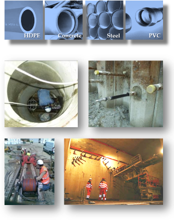
Applications
The DuctRunner™ technology can be deployed in any duct or pipe infrastructure that has pre-determined entry and exit points. The technology is not affected by electromagnetic interferences and can therefore be deployed in steel pipes, near live electricity cables, near railroads, etc. Because the probes operate autonomously, there is no limitation to measurement depth nor does it require above ground tracing.
In the course of a pipe’s lifecycle, there are three opportune moments to collect positional data:
- during new installations
- when a pipe is rehabilitated
- during scheduled maintenance
In each of these stages the system output may be useful for different purposes.
Currently, the most common applications are pipelines installed by trenchless technologies, anchors and freeze holes, upgrade of analog (or digitized) network data to digital data and high definition inclination assessment.


Operational Procedure
